Two new bare boards for PTO experimentation
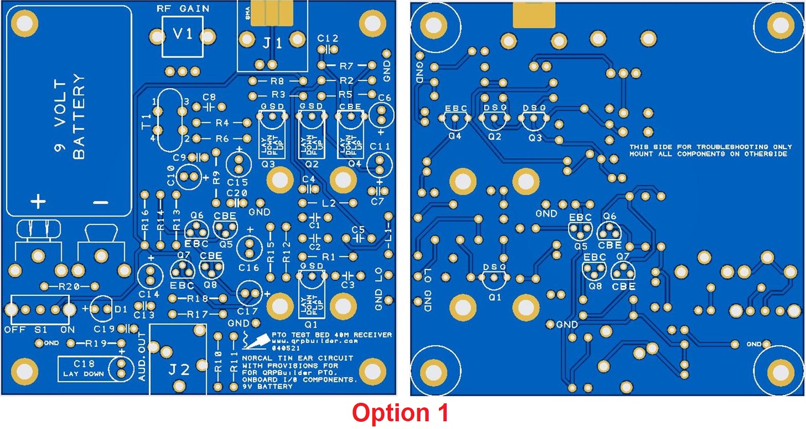
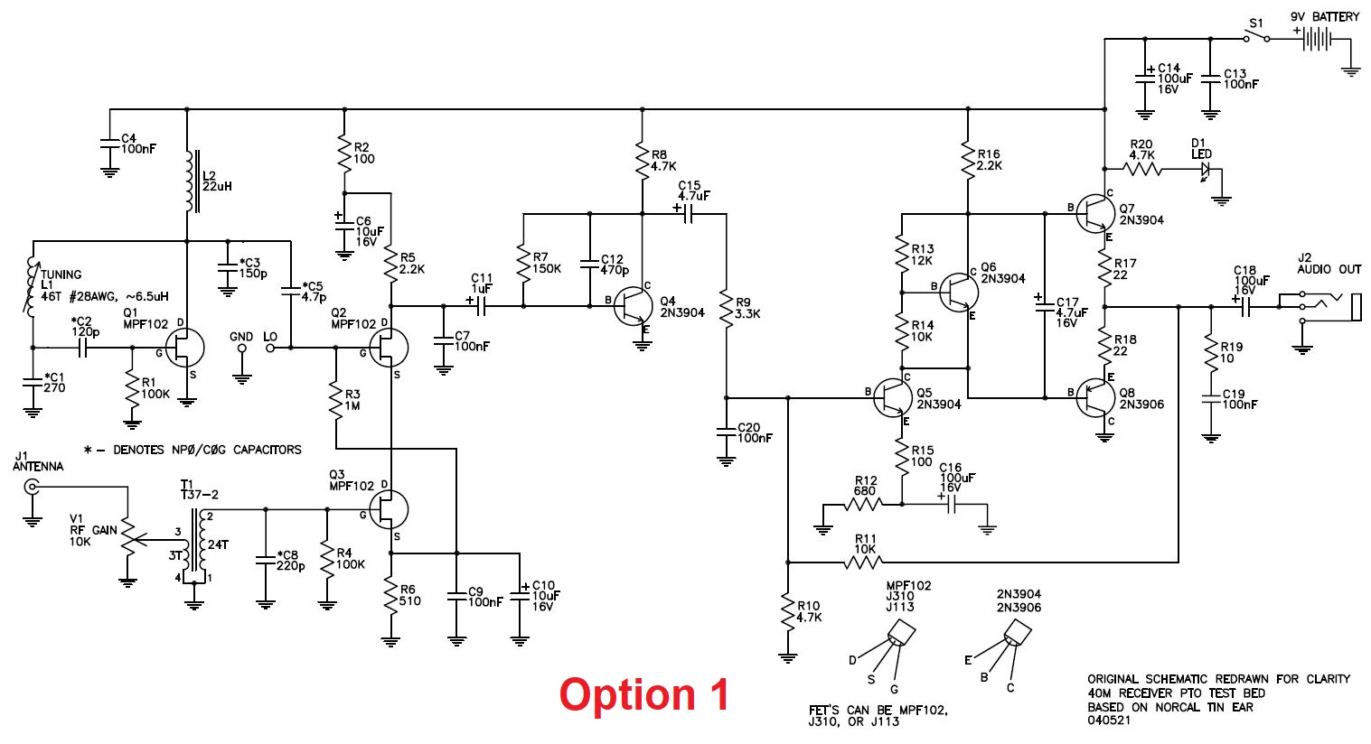
During the design of the PTO Mechanism Kit, I layed out a 3.12” sq. board based on the original Norcal 40m TinEar Receiver, designed by Wayne McFee (NB6M), as a test circuit. I am calling this Option 1. We retained the original Norcal component designations so you can use the original TinEar documentation to source the components. Refering to the pictures below, I added some features listed to make it easier to build and use. For anyone that is not familiar with the TinEar, there are no IC’s, just common transistors and a PTO coil for a stable receiver. With this board, a chassis is not required, as all the components are through hole and board mounted. The original documentation contains component values for additional bands.
Changes included:
- Added onboard 9V battery clips, Mouser # 534-593 and 534-594
- Added D1, power on LED, Tayda A-705
- Added R20, 47K resistor for the LED dropping resistor, A-2066
- Added S1, slide switch for power, Tayda # A-659
- Added BNC female, like eBay # 290684255066 or SMA female
- Added 3.5mm pcb phone jack, Tayda A-069
- Added 10K vertical pcb pot, Tayda A-1850
- Added mounting holes for the PTO
- Added a local oscillator test pad (LO) for aiding the determination of L1
- Added a GND pad for the 3 turn winding on the T1 toroid.
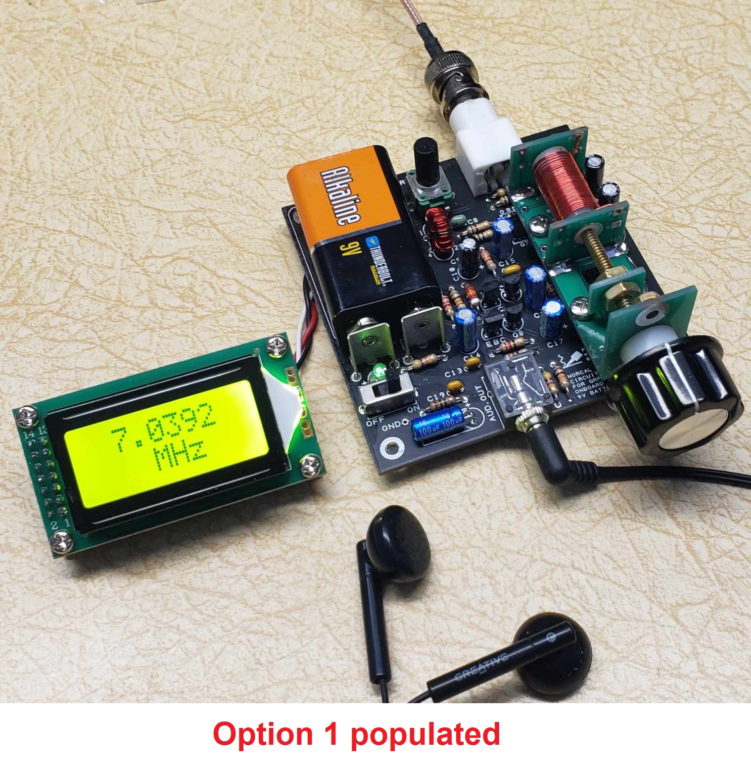
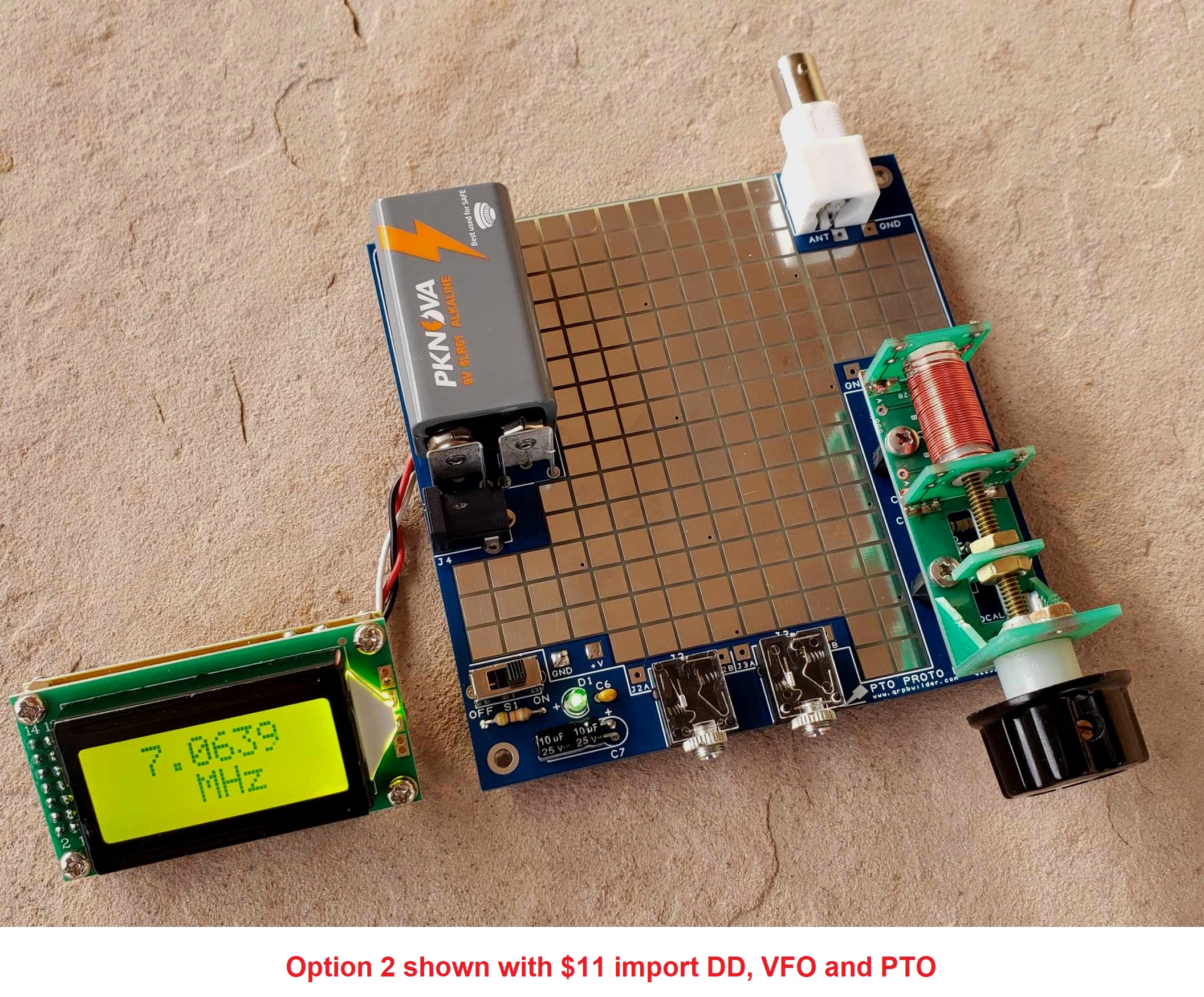
For L1 with my PTO, I used the .37” dia. coil form option with 36 turns of 26AWG close wound to match the calculated 6.5uH of the original L1 from the 40m TinEar design and the brass threaded rod, ending up with 6.990-7.258 MHz coverage. For the PTO (L1), you can use your own, the original Norcal soda straw design, or the PTO mechanism kit is available here.
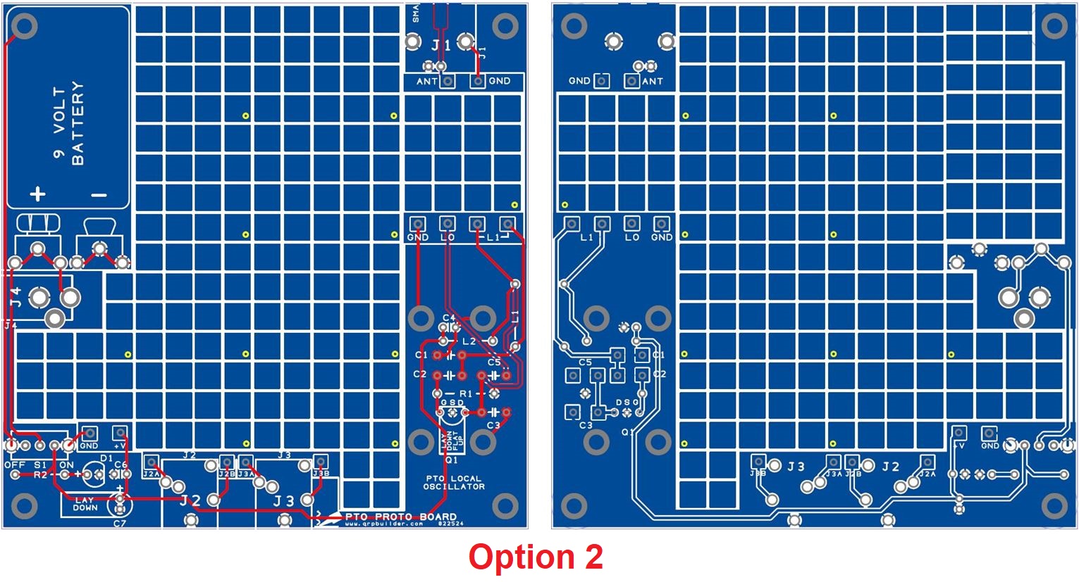
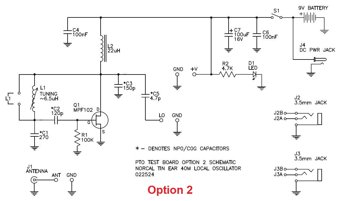
I also have Option 2, for users designing their own circuit, or only the VFO portion of the TinEar. For the same price of $12, and free shipping. Details include a 4.25″ sq. bare board with a large prototype area on both sides and provisions for:
- 171 .20″ sq. top pcb pads, 204 .20″ sq. bottom pcb pads, and 10 vias allowing pass through circuit expansion between the two layers
- onboard 9V battery clips, Mouser # 534-593 and 534-594
- DC aux. 2.1mm power jack mount, Tayda A-4118
- power on LED, Tayda A-705
- 47K LED dropping resistor, A-2066
- slide switch for power, Tayda # A-659
- BNC female, like eBay # 290684255066 or SMA female
- Two 3.5mm pcb stereo phone jacks, Tayda A-069
- mounting holes for the PTO
- local oscillator test pad (LO) for aiding the determination of L1
Original Norcal TinEar Receiver Documentation here.
TinEar schematic redrawn for clarity here.
For support email to qrpbuilder@gmail.com